")
")
")
")
")
$32.00
Manufacturer
YanmarDocument Type
Training TextLanguage
EnglishType of Equipment
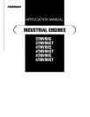
Diesel EngineIllustrated factory Application Manual for Yanmar Diesel Engines Models 3TNV86CT, 3TNV88C, 4TNV86CT, 4TNV88C, 4TNV98C and 4TNV98CT.
This manual will assist you in for your diesel engine.
You can use a Windows, Mac, or Android device to view this manual. You only need to have a PDF reader installed.
Covered Models:
3TNV86CT
3TNV88C
4TNV86CT
4TNV88C
4TNV98C
4TNV98CT
Format: PDF, 546 pages
Language: English
Publication Date: 01 Sep 2013
Table of Contents:
Cover
Application Standard
Application Standard
Special Operating Environment
Low-temperature Startability
Allowable Air Intake Restriction and Exhaust Back Pressures
Emission Control Regulations for Non-road Diesel Engine (Requirements for the Driven Machine Manufacturers)
Engine Model Selection
Model Designation
Engine Classification
Standard Engines for Driven Machines
Specifications
Engine output for industrial use
Engine output for generator use
Specifications
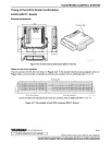
Correcting Observed Power
Power Corrections
Atmospheric Pressure Calculation for Change in Altitude
Atmospheric Temperature Calculation for Change in Altitude
Relationships among Altitude, Atmospheric Pressure and Atmospheric Temperature
How to Obtain Relative Humidity by Dry and Wet-bulb Thermometer
Relationship between Atmospheric Temperature and Saturation Vapor Pressure
Corrections for High Altitudes
Engine Performance
Performance Curves
Torque Curve: T
Partial Recovery Ratio
Governor Performance...JIS B8002-4
Cold Starting Aids
Glow Plug
Engine Block Heater
Air Intake System
Air Capacity Required for Combustion
Air Cleaner
Air Intake Throttle
Air Intake Restriction
Exhaust System
In-use testing requirements
EGR Equipment
Turbocharger
Exhaust Back Pressure
DPF System
Exhaust Muffler
Fitting Precautions for Exhaust System
Exhaust Gas Volume and Exhaust Back Pressure
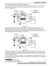
Cooling System
Cooling System Diagram
Engine Coolant
Radiator
Cooling System Hoses
Thermostat
Engine Coolant Temperature Sensor
Engine Coolant Temperature Switch
Cooling System Recovery Tank
Heat Rejection to Engine Coolant
Cooling Fan and Its Drive System
Diesel Fuel System
Fuel inlet label
Fuel Injection System
Diesel Fuel System Diagram
Standard Diesel Fuel Line Layout
Diesel Fuel
Engine Oil Filter System
Fuel Line Maintenance
Lubricating System
Lubricating System Diagram
Engine Oil
Engine Oil Filter System
Oil Pan
Inclined Performance
Crankcase Breather System
Engine Oil Pressure Switch
Engine Oil Cooler
Installation Test Procedures
Purpose of the Installation Test
Test Items and Evaluation Purpose
Tools Required for Tests
Engine Parts Required for Tests
Preparations before the Test
Test and Measurement Procedures
Electrical System
Precautions for Using Electrical Components
Starter Motor
Charging System
Regulator
Control of Battery Indicator
Battery
Wiring
Electronic Control System
Third party’s industrial property
Precautions for Using Electrical Component in the Control System
Control System
Harness
Control Functions
Application Functions
Supply Pump
Rail Pressure Sensor
Crank Rotation Sensor
Cam Speed Sensor
Cooling Water Temperature Sensor
New Air Temperature Sensor
Diesel Particulate Filter (DPF) Inside/Inlet and Exhaust Temperature Sensors
Diesel Particulate Filter (DPF) Differential Pressure Sensor
EGR Pressure Sensor
Intake Temperature Sensor
EGR Temperature Sensor
EGR Valve
intake Air Throttles
Exhaust Air Throttles
Acceleration Sensor
Starter Motor Relay
Glow Plug Relay
EGR Valve Relay
ECU Application Menu
ON-Vehicle Communication CAN Specification
Scope
Communication Protocols
Message Format
Diagnostic Trouble Codes (DTCs)
References
Appendix A
Appendix B
Appendix C
Appendix D
P.T.O. Systems
Direct Coupled P.T.O. Configurations
Caution for Side Load
How to Calculate the Side Load
Allowable Side Load for Main P.T.O.
Allowable Side Load for Front P.T.O.
Cautions for Hydraulic Pump Drive P.T.O. on the Gear Case
Allowable Load for Hydraulic Pump Drive P.T.O.
Vibration Isolation System
Principle of Vibration Isolation
Calculation of Rubber Isolator
Torsional Vibration
What is Torsional Vibration?
Torsional Vibration of Multi-cylinder Engine
Actual Processing for Torsional Vibration
Avoidance and Suppression of Torsional Vibration
Torsional Vibration Equivalent Vibration System
Reference Materials
Principal Conversion Table for the Engine Specifications
Fuel Tank
Oil Pan Holding Time
Mean Piston Speed
Total Displacement
Torque
Net Mean Effective Pressure
Fuel Injection
Cyclic Irregularity (or Coefficient of Speed Fluctuation)
Thermal Efficiency and Heat Loss
Generator
Hydraulic Pump (Gear)
Water Pump Driving Horsepower (Required Horsepower)
Form Characteristics of Cooling Fan
Mesh Number and Size of Mesh
Centigrade-Fahrenheit Temperature Conversion
Hill Climbing Horsepower and Allowable Climbing Angle
Conversion Factors for SI Units
This manual will assist you in for your diesel engine.
You can use a Windows, Mac, or Android device to view this manual. You only need to have a PDF reader installed.
Covered Models:
3TNV86CT
3TNV88C
4TNV86CT
4TNV88C
4TNV98C
4TNV98CT
Format: PDF, 546 pages
Language: English
Publication Date: 01 Sep 2013
Table of Contents:
Cover
Application Standard
Application Standard
Special Operating Environment
Low-temperature Startability
Allowable Air Intake Restriction and Exhaust Back Pressures
Emission Control Regulations for Non-road Diesel Engine (Requirements for the Driven Machine Manufacturers)
Engine Model Selection
Model Designation
Engine Classification
Standard Engines for Driven Machines
Specifications
Engine output for industrial use
Engine output for generator use
Specifications
Correcting Observed Power
Power Corrections
Atmospheric Pressure Calculation for Change in Altitude
Atmospheric Temperature Calculation for Change in Altitude
Relationships among Altitude, Atmospheric Pressure and Atmospheric Temperature
How to Obtain Relative Humidity by Dry and Wet-bulb Thermometer
Relationship between Atmospheric Temperature and Saturation Vapor Pressure
Corrections for High Altitudes
Engine Performance
Performance Curves
Torque Curve: T
Partial Recovery Ratio
Governor Performance...JIS B8002-4
Cold Starting Aids
Glow Plug
Engine Block Heater
Air Intake System
Air Capacity Required for Combustion
Air Cleaner
Air Intake Throttle
Air Intake Restriction
Exhaust System
In-use testing requirements
EGR Equipment
Turbocharger
Exhaust Back Pressure
DPF System
Exhaust Muffler
Fitting Precautions for Exhaust System
Exhaust Gas Volume and Exhaust Back Pressure
Cooling System
Cooling System Diagram
Engine Coolant
Radiator
Cooling System Hoses
Thermostat
Engine Coolant Temperature Sensor
Engine Coolant Temperature Switch
Cooling System Recovery Tank
Heat Rejection to Engine Coolant
Cooling Fan and Its Drive System
Diesel Fuel System
Fuel inlet label
Fuel Injection System
Diesel Fuel System Diagram
Standard Diesel Fuel Line Layout
Diesel Fuel
Engine Oil Filter System
Fuel Line Maintenance
Lubricating System
Lubricating System Diagram
Engine Oil
Engine Oil Filter System
Oil Pan
Inclined Performance
Crankcase Breather System
Engine Oil Pressure Switch
Engine Oil Cooler
Installation Test Procedures
Purpose of the Installation Test
Test Items and Evaluation Purpose
Tools Required for Tests
Engine Parts Required for Tests
Preparations before the Test
Test and Measurement Procedures
Electrical System
Precautions for Using Electrical Components
Starter Motor
Charging System
Regulator
Control of Battery Indicator
Battery
Wiring
Electronic Control System
Third party’s industrial property
Precautions for Using Electrical Component in the Control System
Control System
Harness
Control Functions
Application Functions
Supply Pump
Rail Pressure Sensor
Crank Rotation Sensor
Cam Speed Sensor
Cooling Water Temperature Sensor
New Air Temperature Sensor
Diesel Particulate Filter (DPF) Inside/Inlet and Exhaust Temperature Sensors
Diesel Particulate Filter (DPF) Differential Pressure Sensor
EGR Pressure Sensor
Intake Temperature Sensor
EGR Temperature Sensor
EGR Valve
intake Air Throttles
Exhaust Air Throttles
Acceleration Sensor
Starter Motor Relay
Glow Plug Relay
EGR Valve Relay
ECU Application Menu
ON-Vehicle Communication CAN Specification
Scope
Communication Protocols
Message Format
Diagnostic Trouble Codes (DTCs)
References
Appendix A
Appendix B
Appendix C
Appendix D
P.T.O. Systems
Direct Coupled P.T.O. Configurations
Caution for Side Load
How to Calculate the Side Load
Allowable Side Load for Main P.T.O.
Allowable Side Load for Front P.T.O.
Cautions for Hydraulic Pump Drive P.T.O. on the Gear Case
Allowable Load for Hydraulic Pump Drive P.T.O.
Vibration Isolation System
Principle of Vibration Isolation
Calculation of Rubber Isolator
Torsional Vibration
What is Torsional Vibration?
Torsional Vibration of Multi-cylinder Engine
Actual Processing for Torsional Vibration
Avoidance and Suppression of Torsional Vibration
Torsional Vibration Equivalent Vibration System
Reference Materials
Principal Conversion Table for the Engine Specifications
Fuel Tank
Oil Pan Holding Time
Mean Piston Speed
Total Displacement
Torque
Net Mean Effective Pressure
Fuel Injection
Cyclic Irregularity (or Coefficient of Speed Fluctuation)
Thermal Efficiency and Heat Loss
Generator
Hydraulic Pump (Gear)
Water Pump Driving Horsepower (Required Horsepower)
Form Characteristics of Cooling Fan
Mesh Number and Size of Mesh
Centigrade-Fahrenheit Temperature Conversion
Hill Climbing Horsepower and Allowable Climbing Angle
Conversion Factors for SI Units
General
Manufacturer
YanmarDocument Type
Training TextLanguage
EnglishType of Equipment
Diesel EngineReviews: 0
There are no reviews for this product.
Questions: 0
No questions about this product.
Similar Products
")
3TN86CT,3TN88C,3TNV88C, 4TN86CT,4TN88C, 4TN98C,4TNV86CT, 4TNV88C, 4TNV98C Diesel Engines Troubleshooting Manual (0DTN5-EN1023)
0DTN5-EN1023
Manufacturer: Yanmar
Document Type: Troubleshooting Manual
Language: English
Type of Equipment: Diesel Engine
$32.00
")
3TNV82A, 3TNV84, 3TNV88, 4TNV106, 4TNV84, 4TNV88, 4TNV94L, 4TNV98 Diesel Engines Troubleshooting Manual (0DTNV-G00600)
0DTNV-G00600
Manufacturer: Yanmar
Document Type: Troubleshooting Manual
Language: English
Type of Equipment: Diesel Engine
$32.00
 Service Manual (HINSHI-H8013-R1)")
4TNE106, 4TNE106T, 4TNE94 and 4TNE98 Diesel Engines (Base Engine) Service Manual (HINSHI-H8013-R1)
HINSHI-H8013-R1
Manufacturer: Yanmar
Document Type: Service Manual
Language: English
Type of Equipment: Diesel Engine
$32.00

3TNV82A-Z,3TNV84T-Z,3TNV88-E,3TNV88-Z,4TNV84T-Z,4TNV88-E,4TNV98-E/Z,4TNV98T-Z Diesel Engine Electronic Control Technical Manual
YANMAR::TNV_ECM
Manufacturer: Yanmar
Document Type: Technical Manual
Language: English
Type of Equipment: Diesel Engine
$32.00
")
2TNV70,3TNV70,3TNV76,3TNV82A,3TNV84,3TNV88, 4TNV84,4TNV88,4TNV94L,4TNV98 Engines Electrical System Repair Manual (TNVELECSERV)
TNVELECSERV
Models: 2TNV70, 3TNV70, 3TNV76, 3TNV82A, 3TNV84, 3TNV84T, 3TNV88, 4TNV84, 4TNV84T, 4TNV88, 4TNV94L, 4TNV98, 4TNV98T
Document Type: Repair Technical Manual
Language: English
Type of Equipment: Diesel Engine
$25.00