$49.99
Document Type
Service ManualRegion
WorldWideLanguage
EnglishType of Equipment
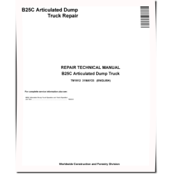
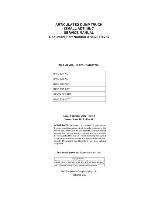
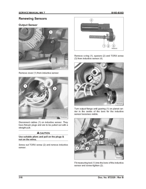
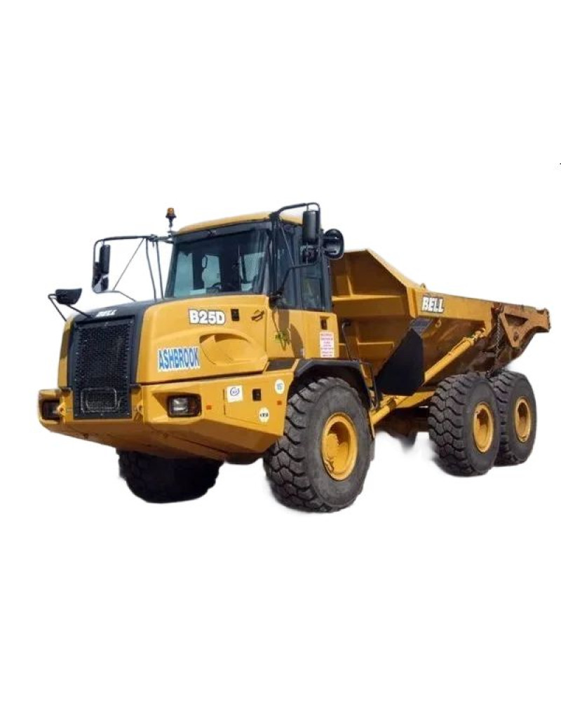
Articulated Dump TruckIllustrated factory Service Manual for BELL Articulated Dump Trucks Models B18D 6X4, B18D 6X6, B20D 6X4, B25D 6X6, B25DN 6X6 and B30D 6X6.
This manual will assist you in diagnosing, analyses, testing, and repair for your articulated dump truck.
You can use a Windows, Mac, or Android device to view this manual. You only need to have a PDF reader installed.
Covered Models:
B18D 6X4 (Mk 7)
B18D 6X6 (Mk 7)
B20D 6X4 (Mk 7)
B25D 6X6 (Mk 7)
B25DN 6X6 (Mk 7)
B30D 6X6 (Mk 7)
Format: PDF, 495 pages
Language: English
Publication Date: 01 Jun 2012
Table of Contents:
SAFETY 17
Specification 17
General 17
Safety Features 17
Material Safety Data Sheet (MSDS) 18
Unauthorised Modifications of ROPS and FOPS 18
Loosening or Removal Of ROPS and FOPS 18
Noise Emission Levels 18
Safety Regulations 19
General Safety 19
TYRE INFORMATION 30
Tyres and Rims 30
Tyre Pressures - General 30
Tyre Pressures - Inflation Pressure, Hot vs. Cold 30
OPERATIONAL CHECK-OUT PROCEDURE 35
Operational Check 35
Ignition Button Pressed ONCE, Engine OFF 35
Ignition Button Pressed (Second Stage), Engine Start 36
Engine Stop Button Pressed 38
ENGINE 39
Engine (OM 906 LA Shown) 39
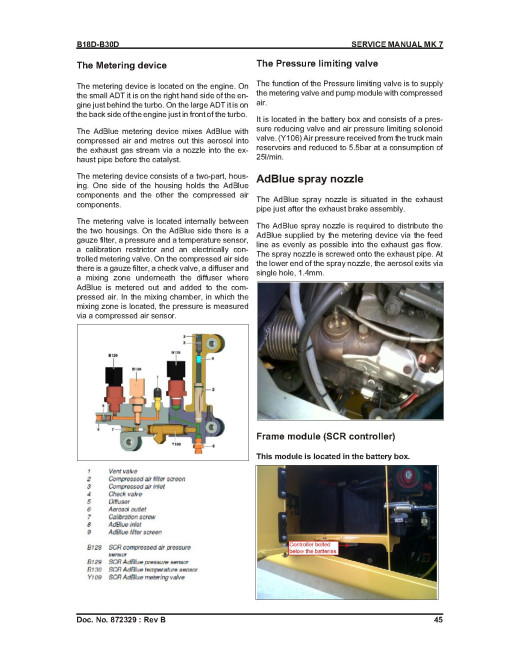
SCR 44
SCR - Components 44
The Metering device 45
Display Menu Tachometer (B20D Shown) 53
Slow and Fast Idle Adjustment 53
Valve Clearance Adjustment 53
Exhaust Brake Adjustment 54
Oil Pump Pressure Test 60
ELECTRICAL SYSTEM 63
Schematics 63
Electrical Schematic Symbols 63
Electrical Schematics 64
Earth Connections 91
Fuse and Relay Layout 91
ADM-Mercedes ECU Inputs and Outputs 105
a. ELECTRICAL SYSTEM - Connectors 111
Connectors 111
b. Fault Codes & MDU Fault Display 153
Engine Fault Codes (ADM) 153
Engine Fault Codes (PLD-MR) 162
CCU, MDU & OEU Fault Codes 178
c. MDU Menu Structure 193
General Description 239
MDU3 Menu Structure 193
Default Display 196
Accessing Service Mode 198
Main Menu 199
Specifications and Tests 229
TRANSMISSION 239
Planetary Gears Sets 244
Transmission Cross Sectional Diagram 246
Power Flow 247
Functional Description Hydraulic System 248
General Description 254
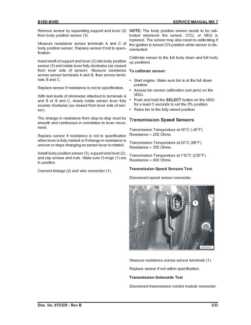
Speed Sensors 257
Control Module 257
Wiring Harnesses 258
Autodetect Feature 261
Hydraulic Circuits 263
Neutral to Drive Transition 265
st Range Operation 265
st Range to 2nd Range Transition 266
Torque Converter And Lube Pressure Circuits 277
Exhaust Backfill Pressure 277
Definitions And Abbreviations 278
Identification of Potential Circuit Problems 293
Oil Level Sensor (OLS) 284
Diagnostic Code Memory 286
TRANSMISSION ZF 6 HP 592 C PLUS 295
General Descriptions 295
Stall Speeds 299
Stall Speeds (Blu@dvantage) 299
Planetary Gears and Power Flows 300
Hydraulic System 306
Valve Schematic 1 307
Retarder Lever 312
ZF Gear Shift Control 313
Internal Solenoids 315
Renewing Sensors 318
External Solenoids 325
Diagnostic Codes 325
Transmission Control Unit Error Codes 334
PNEUMATIC SYSTEM 353
Pneumatic System Schematic 353
Pneumatic System Operation 355
Fault Finding 360
Adjustments and Tests 362
Pneumatic System Main Pressure Test and Adjustment 362
Park Brake Pressure Test 362
Park Brake Adjustment 363
HYDRAULIC SYSTEM 367
Hydraulic System Circuit Symbols 367
Hydraulic Schematic B18D and B20D Without Wet Disc Brakes 368
Hydraulic Schematic B25D and B30D Without Wet Disc Brakes 369
Hydraulic Schematic B30D With Wet Disc Brakes 370
Articulated Dump Truck Hydraulic System Operation 371
Main Hydraulic Pump Operation 373
Main Hydraulic Pump Load Sense Operation 374
Steering Valve Operation 376
Secondary Steering Pump Operation 378
Hydraulic System Manifold (Front View) 381
Hydraulic System Manifold (Rear View) 382
Hydraulic System Manifold (Right View) 383
Manifold Schematic 384
General Description 385
Service Brake System Operation 386
Steering And Secondary Steering System Operation 387
Bin Operation 388
Diagnostic Procedure 391
Tests and Adjustments 400
Digital Thermometer Installation 400
Digital Analogue Pressure/Temperature Analyser Installation 400
Hydraulic Oil Cleanup Procedure Using Portable Filter Caddy 401
Hydraulic System Warm-Up Procedure 401
Setting Hydraulic Pressure 402
Activate the Hydraulic Pressure Setup Mode: 403
Calibrate the Bin Position Sensors: 403
Set the Emergency Steering Pump Pressures 403
Set the Emergency Steering Pump Residual Pressure 403
Set the Emergency Steering Pump Compensating Pressure: 404
Set the Main Pump Residual Pressures B18/B30 405
Set the Main Pump Compensating Pressure B18/B30 405
Set the Steering Pressure 407
Set the Brake Circuit Pressures: 407
Accumulator Charge Pressure Check and Re-charge Procedure 409
Set the Bin Tip Pilot Pressure 410
Cycle Time Test 411
HEATING, VENTILATION AND AIR CONDITIONING 413
Air Conditioning System Cycle Of Operation 413
Heater Core Operation 414
Tests 419
Operational Checks 419
R134A Air Conditioning System Test 420
Air Freeze Control Switch Test 422
Air Compressor Clutch Test 422
Air High/Low Pressure Switch Test 422
Air Expansion Valve Test 423
Expansion Valve Bench Test 424
Refrigerant Leak Test 425
SERVICING, SCHEDULES & LUBRICATION CHART 429
Hydraulic System Overview 429
De-pressurising the Hydraulic System 429
Engine Oil 430
Service Schedules - Pg 1 of 2 435
Service Schedules - Pg 2 of 2 436
HOURS SERVICE AND CHECKS 441
Service Instructions 441
HOURS SERVICE AND CHECKS 445
Service Instructions 445
Change Engine Oil And Replace Filter 445
Check Engine Air Intake System 445
Drain the Racor Fuel Filter 445
Check for oil leaks 446
Tilt and lower the cab 446
Loosen Cab Mounting Bolts Front And Rear Left Hand Side 446
Lower The Cab 447
The Transmission Fluid Level 447
Dipstick Check - Transmission Fluid COLD (Cold Check) 447
Dipstick Check - Transmission Fluid HOT (Hot Check) 448
Check Park Brake Pad Wear 449
Check Service Brake Pad Wear 449
Check The Transfer Case Fluid Level 450
Check Front Axle Suspension Struts 450
General Check Drive Line & Suspension Fasteners 451
Transfer Case Breather (Located under the Hydraulic Reservoir) 451
Transmission Breather And Axle Breathers 451
Middle Axle Breather 451
Rear Axle Breather 452
Inspect, Clean And Replace Cab Air Filter 452
Check Batteries, Clean And Tighten Terminals 453
Check Electrical Connectors, Harnesses And Looms 453
Check Work Lights, Reverse Buzzer And Horns 453
Record & Delete Fault Codes On The MDU 453
Check The Operator Controls And Instruments 454
Grease All Grease Points 454
Lubricate Bin Pivots 454
Articulation Joints, Oscillation Tube Through Drive Shaft Bearing Front And Steering Cylinders Rear Pivot Points 454
Oscillation Tube And Oscillation Tube Through Drive Shaft Bearing Rear 454
Grease Tailgate Pivot Points (If Equipped) 455
Check Hydraulic Oil Level 455
Service Brake Accumulator Routine Test 455
Replace Hydraulic Reservoir Breather 455
Grease Prop Shaft Slip Joint 456
Check Bin Shock Pad Clearance 456
Bin Pad Spacing (Field spacing only) 457
Clean Headlights 458
HOURS SERVICE AND CHECKS 459
Service Instructions 459
Adjust Engine Valve Clearance 459
Replace Primary Fuel Filter (Water Separator) 459
Replace Secondary Fuel Filter 459
Replace Crankcase Breather Filter 459
Remove Tappet Cover 459
Remove Tappet Cover 459
Change the Primary Filter Element 460
Check Coolant Condition 461
Check The Fan Belt Condition 461
Replace Hydraulic Oil Return Filter 462
Check Axle Oil Level 463
Check Final Drive Oil Levels 463
HOURS SERVICE AND CHECKS 465
Service Instructions 465
Change the Secondary Filter Element 465
Change Transmission Oil 465
Drain Transmission Oil Cooler 465
Replace Transmission Oil Filters 466
Fill Transmission 466
Change Transfer Case Oil 466
Change Axle Oil 467
Change Final Drive Oil 468
Check Service Brake Disc Thickness 468
Check Front Hubs 468
Replace Pneumatic System Dryer Filter 469
SCR Pump Module Accumulator Test & Pressure 469
HOURS SERVICE AND CHECKS 471
Service Instructions 471
Change jockey pulley bearing (Tensioner Pulley) 471
Remove Idler Pulley Assembly 471
Change Aircon Pulley Assembly 472
Change all axle driveline cross and rollers 472
Replace The Suction Screen 472
HOURS SERVICE AND CHECKS 473
Service Instructions 473
Replace Fan Belt 473
Change Hydraulic Oil 473
Fill Hydraulic Tank 474
Change Pneumatic Block Breather Filters 474
AS REQUIRED SERVICE 475
Introduction 475
Service Instructions 475
Check the Engine Compartment Components 475
Clean/Replace Primer Pump Fuel Screen 476
Prime fuel system 476
Change Engine Coolant 477
Clean Cooling System 478
Check for Oil and Fuel Leaks 478
Clean the Air Cleaner Pre-cleaner Bowls 478
Clean Air Conditioning Filters 478
Grease Hinges 478
Check And Clean Coolers 478
Hydraulic Oil Cleanliness Sampling Procedure 478
MISCELLANEOUS SERVICE AND CHECKS 481
Service Instructions 481
Inspect Serpentine Belt 481
Change Wheels 481
Using Battery Charger 481
Replace Batteries 482
Replace Front Turn Signal Bulb, Headlight Bulb and Front Park Light Bulb 482
Replace Front Turn Signal Bulb 483
Replace Headlight Bulb 483
Replace Front Park Light Bulb 483
Reassemble Headlight Assembly 483
Adjust Headlights 483
Replace Backup Light and Work Light (If Equipped) 484
Replace Tail and Brake Light and Rear Turn Signal Light 484
Replace Dome Light Bulb and Circuit Breaker Compartment Light Bulb 484
STORAGE AND PRESERVATION 485
Introduction 485
General 485
Category 1 - Laid up for up to 12 months 485
Category 2 - Laid up for 12 to 36 months 486
Category 3- Laid up for up more than 36 months 486
TROUBLE SHOOTING 487
General
Document Type
Service ManualRegion
WorldWideLanguage
EnglishType of Equipment
Articulated Dump TruckReviews: 0
There are no reviews for this product.
Questions: 0
No questions about this product.
Similar Products

