$60.00
Manufacturer
HagieDocument Type
Diagnostic ManualRegion
WorldWideLanguage
EnglishType of Equipment
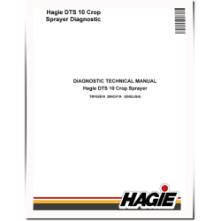
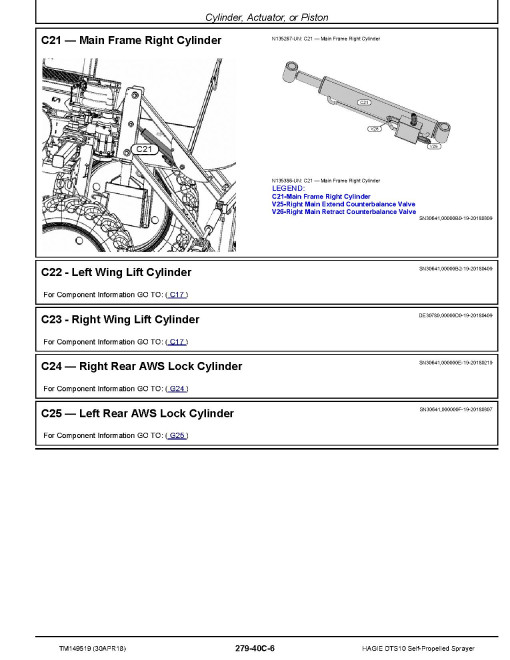
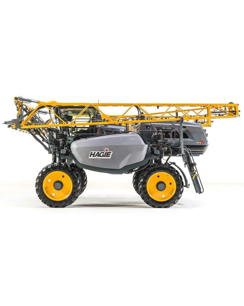
Self-Propelled SprayerIllustrated factory Diagnostic Manual for Hagie Self-Propelled Sprayers Models DTS10.
This manual will assist you in diagnosing for your self-propelled sprayer.
You can use a Windows, Mac, or Android device to view this manual. You only need to have a PDF reader installed.
Covered Models:
DTS10 (SN: 016001-017500)
Format: PDF, 795 pages
Language: English
Publication Date: 30 Apr 2018
Table of Contents:
Introduction
Foreword
General Information
Safety
General References
References for Technical Information
Diagnostic Trouble Codes
Display Diagnostic Trouble Codes
ECU Diagnostic Trouble Codes
Primary Machine Module Diagnostic Trouble Codes
Electrical
General Information
Operational and Preliminary Checks
Theory - Accessories
Theory - Application System
Theory - Attachment
Theory - Boom
Theory - Cab
Theory - Controller Area Network (CAN) bus
Theory - Engine (T3)
Theory - Engine (T4)
Theory - Hydraulics
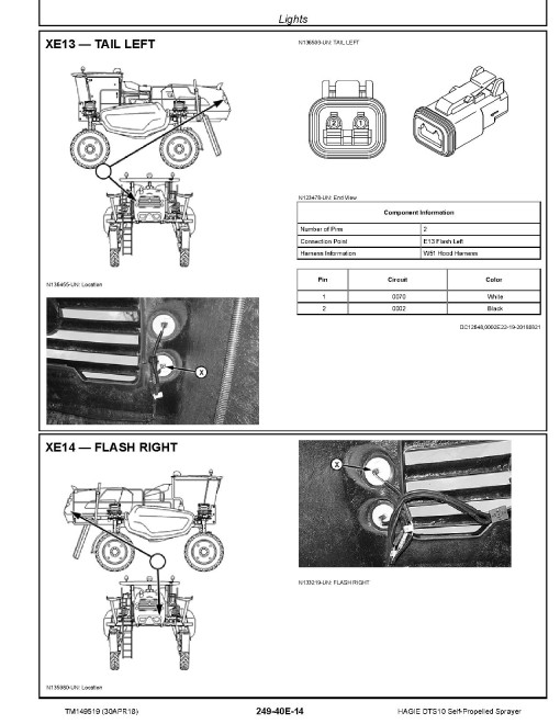
Theory - Lights
Theory - Powertrain
Theory - Start Charge And Power Distribution
Schematic - Accessories
Schematic - Application System
Schematic - Attachment
Schematic - Boom
Schematic - Cab
Schematic - Controller Area Network (CAN) Bus
Schematic - Engine (T3)
Schematic - (T4)
Schematic - Hydraulics
Schematic - Lights
Schematic - Powertrain
Schematic - Start Charge and Power Distribution
Diagnostic Tests and Adjustments
Electronic Control Units
General Information
Operational and Preliminary Checks
Interactive Tests and Calibrations
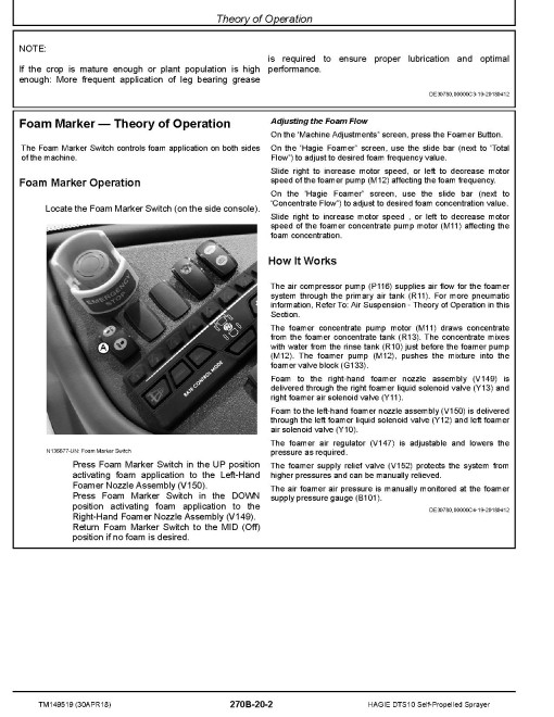
Theory of Operation
Schematic
Diagnostic Tests and Adjustments
Electrical Component Information
General Information
Electrical Assemblies
Sensors
Lights
Fuses
Charging
Monitoring Devices
Relays
Motors
Resistors
Switches
Interconnects and Ground Points
Electronically Actuated Mechanical Devices
Drivetrain
General Information
Operational and Preliminary Checks
Theory of Operation
Schematic
Diagnostic Tests and Adjustments
Drivetrain Component Information
General Information
Steering
General Information
Operational and Preliminary Checks
Theory of Operation
Schematic
Diagnostic Tests and Adjustments
Park Brake
General Information
Operational and Preliminary Checks
Theory of Operation
Schematic
Diagnostic Tests and Adjustments
Tread Adjust
General Information
Operational and Preliminary Checks
Theory of Operation
Schematic
Diagnostic Tests and Adjustments
Steering and Brakes Component Information
General Information
Hydraulics
General Information
Operational and Preliminary Checks
Theory of Operation
Schematic
Diagnostic Tests and Adjustments
Pneumatics
General Information
Test Procedures and Adjustments
Theory of Operation
Schematic
Diagnostic
Hydraulics Component Information
General Information
Accumulators
Sensor or Gauge
Cylinder, Actuator, or Piston
Check Valve
Filter
Valve Block, Assembly, or Gearcase
Cooler
Motor
Orifice
Pump
Reservoir or Tank
Valve
Mechanical Assembly
Diagnostic Receptacle or Coupler
Solenoid Valve
Solution System
General Information
Theory of Operation
Schematics
Diagnostics
Solution System Component Information
General Information
Accumulators
Sensors
Check Valves
Filters
Valve Block, Assembly, or Gearcase
Motors
Orifices
Pumps
Reservoirs
Valves
Diagnostic Receptacle or Coupler
Solenoid Valve
Tools
General Information
Dealer Fabricated Tools
Special Tools
Section 260A
Section 260B
Section 260C
Section 270A
Section 270B
General
Manufacturer
HagieDocument Type
Diagnostic ManualRegion
WorldWideLanguage
EnglishType of Equipment
Self-Propelled SprayerReviews: 0
There are no reviews for this product.
Questions: 0
No questions about this product.
Similar Products

