
$60.00
Manufacturer
John DeereDocument Type
Technical ManualLanguage
EnglishType of Equipment
Gator Utility VehicleIllustrated factory Technical Manual for John Deere Gator Utility Vehicles Models XUV825M S4.
This manual will assist you in diagnosing, and repairing for your gator utility vehicle.
You can use a Windows, Mac, or Android device to view this manual. You only need to have a PDF reader installed.
Covered Models:
XUV825M S4 (SN: 040001-)
Format: PDF, 751 pages
Language: English
Publication Date: 08 Sep 2021
Table of Contents:
Introduction
Foreword
General Information-Repair
Safety
General Specifications
Fuel and Lubricants
Machine Specifications
Engine Repair
General Information
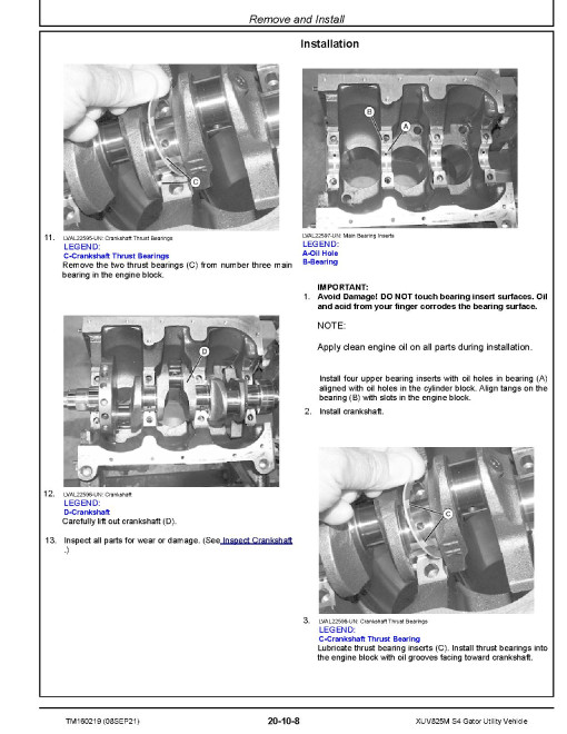
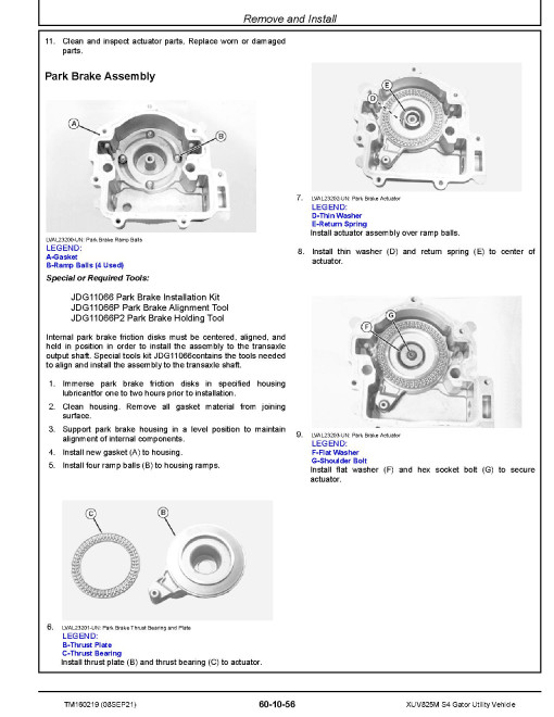
Remove and Install
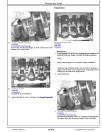
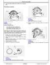
Disassemble and Assemble
Inspect
Fuel, Air, and Cooling System Repair
General Information
Remove and Install
Disassemble and Assemble
Electrical Repair
General Information
Remove and Install
Drivetrain Repair
General Information
Remove and Install
Disassemble and Assemble
Inspect
Steering and Brake Repair
General Information
Remove and Install
Attachment and Machine-Specific Repair
General Information
Remove and Install
Operator Station Repair
General Information
Remove and Install
General Information - Diagnostics
General Information
Diagnostic Trouble Codes
Control Unit ICC
Control Unit ECU
Control Unit SCU
System Diagnostics Access
Engine System Diagnostics
Fuel, Air Intake, and Cooling System
Electrical System
Electrical Control Units
Steering and Brake Systems
Attachment/Machine-Specific Systems
Engine System Diagnostics
General Information
Operational and Preliminary Checks
Theory of Operation
Test and Adjustments
Diagnostics
Fuel, Air Intake, and Cooling System Diagnostics
General Information
Theory of Operation
Schematics
Tests and Adjustments
Diagnostics
Electrical System Diagnostics
General Information
Theory of Operation - Starting, Charging, and Power Distribution
Theory of Operation - Steering and Brakes
Theory of Operation - Operator Station
Theory of Operation - CAN Bus
Theory of Operation - Engine
Theory of Operation - Lighting
Theory of Operation - Drivetrain
Theory of Operation - Fuel, Air, and Cooling
Schematics - Starting, Charging, and Power Distribution
Schematics - Steering and Brakes
Schematics - Operator Station
Schematics - CAN Bus
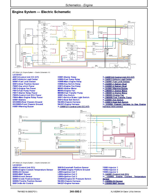
Schematics - Engine
Schematics - Lighting
Schematics - Drivetrain
Schematics - Fuel, Air, and Cooling
Tests and Adjustments
Diagnostics - Starting, Charging, Power Distribution
Diagnostics - Steering and Brakes
Diagnostics - Operator Station
Diagnostics - CAN Bus Systems
Diagnostics - Engine Systems
Diagnostics - Lighting
Diagnostics - Drivetrain
Diagnostics - Fuel, Air, Exhaust, and Cooling
Electrical Control Unit Diagnostics
General Information
Theory of Operation
Schematics
Diagnostics
Electrical System - Connectors
General Information
XA - Electrical Assembly Connectors
XB - Sensor Connectors
XE - Lighting Connectors
XF - Fuse Connectors
XG - Charging Connectors
XH - Alarm Connectors
XK - Relay Connectors
XL - Inductor Connectors
XM - Motor Connectors
XS - Switch Connectors
XV-Diode Connectors
XX - Inline Connectors
XY - Solenoid Connectors
Drivetrain System Diagnostics
Theory of Operation
Tests and Adjustments
Diagnostics
Steering and Brake System Diagnostics
Theory of Operation
Schematics
Tests and Adjustments
Diagnostics
Attachment and Machine-Specific System Diagnostics
Theory of Operation
Diagnostics
Operator Station Diagnostics
Tests and Adjustments
Special Tools
Service Tools and Kits
General
Manufacturer
John DeereDocument Type
Technical ManualLanguage
EnglishType of Equipment
Gator Utility VehicleReviews: 0
There are no reviews for this product.
Questions: 0
No questions about this product.
Similar Products

