$60.00
Manufacturer
John DeereDocument Type
Technical ManualLanguage
EnglishType of Equipment
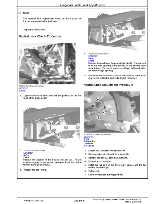
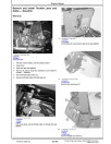
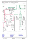
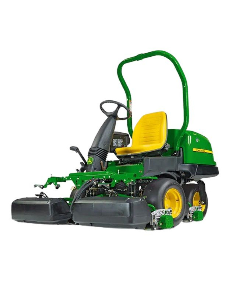
Riding MowerIllustrated factory Technical Manual for John Deere E-Cut Hybrid Riding Mowers Models 2550, PrecisionCut Riding Mowers Models 2400 and 2550.
This manual will assist you in diagnosing, and repairing for your riding mower.
You can use a Windows, Mac, or Android device to view this manual. You only need to have a PDF reader installed.
Covered Models:
E-Cut Hybrid 2550 (SN: 010001-)
PrecisionCut 2400 (SN: 010001-)
PrecisionCut 2550 (SN: 010001-)
Format: PDF, 722 pages
Language: English
Publication Date: 26 May 2020
Table of Contents:
Introduction
Foreword
General Information
Safety
General Specifications
Fuel, Lubricants, and Coolants
Machine Specifications
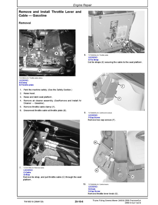
Engine Repair - Gasoline
General Information
Engine Repair
Engine Repair - Diesel
Diesel Repair
Electrical Repair
Battery
Electrical System Components
Electrical Repair
Power Train Repair
Repair
Hydraulic Repair
Hydraulic Repair
Hydraulic Pumps Repair
Hydraulic Attachments
Brakes Repair
Brake Repair
Steering Repair
Steering
Attachments Repair
Reel Motor
QA5 Reel
Cutting Unit Attachments
Miscellaneous Repair
Wheels
Operator Station
Fuel System
General Information - Diagnostics
General Information
Engine - Gas Operation, Tests, and Adjustments
General Information
Operational and Preliminary Checks
Theory of Operation
Tests and Adjustments
Diagnostics
Engine - Diesel Operation, Tests, and Adjustments
Theory of Operation
Tests and Adjustments
Diagnostics
Electrical Operation, Tests, and Adjustments
General Information
Theory of Operation - Gasoline
Theory of Operation - Diesel
Wiring Schematics - Gasoline
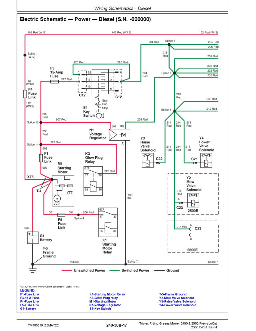
Wiring Schematics - Diesel
Tests and Adjustments
Diagnostics - Gasoline
Diagnostics - Diesel
Diagnostics - Reel Motor Controllers
Electrical Control Units
General Information
Theory of Operation
Schematics
Electrical System - Component Information
General Information
XA - Electrical Assembly Connectors
XB - Sensor Connectors
XE - Light Connectors
XF - Fuse Connectors
XG - Charging Connectors
XK - Relay Connectors
XM - Motor Connectors
XN - Regulator Connectors
XR - Resistor Connectors
XS - Switch Connectors
XV - Diode Connectors
XW - Terminals
XX - Inline Connectors
XY - Solenoid Connectors
Power Train Operation, Tests, and Adjustments
Theory of Operation
Hydrostatic Schematics
Component Location
Diagnosis, Tests, and Adjustments
Brakes Operation, Tests, and Adjustments
Theory of Operation
Component Location
Diagnosis, Tests, and Adjustments
Steering Operation, Tests, and Adjustments
Theory of Operation
Component Location
Diagnosis, Tests, and Adjustments
Hydraulics Operation, Tests, and Adjustments
Theory of Operation
Hydraulic Schematics
Component Location
Diagnosis, Tests, and Adjustments
Attachments Operation, Tests, and Adjustments
Theory of Operation
Component Location
Diagnosis, Tests, and Adjustments
Service Tools and Kits
Service Tools
Section 260A
Section 260B
General
Manufacturer
John DeereDocument Type
Technical ManualLanguage
EnglishType of Equipment
Riding MowerReviews: 0
There are no reviews for this product.
Questions: 0
No questions about this product.
Similar Products

