$90.00
Manufacturer
John DeereDocument Type
Diagnostic ManualRegion
South AmericaLanguage
EnglishType of Equipment
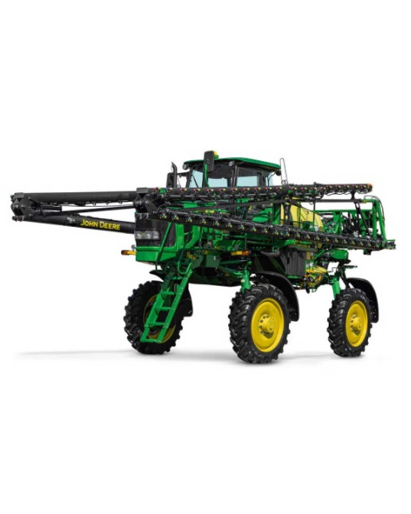
Self-Propelled SprayerIllustrated factory Diagnostic Manual for John Deere Sprayers Models M4025.
This manual will assist you in diagnosing for your sprayer.
You can use a Windows, Mac, or Android device to view this manual. You only need to have a PDF reader installed.
Covered Models (South America):
M4025 (SN: 180000-189999)
Format: PDF, 1128 pages
Language: English
Publication Date: 18 Dec 2018
Table of Contents:
Introduction
Foreword
General Information
Safety
Torque Values
Diagnostic Trouble Codes
BHC - Boom Hydraulics Control Unit
CCU - Chassis Control Unit
ECU - Engine Control Unit
iTC - Integrated Terrain Compensation
JDLink / ZXLink Control Unit
JDLink 2 Control Unit
SRC - Spray Rate Control Unit
SSU - Steering Control Unit
TEC - Tractor Equipment Control Unit
TEI - Tractor Equipment Interface
Observable Symptoms
Engine
Air Intake and Cooling Systems
Electrical Systems
Power Train Systems
Brake Systems
Hydraulic Systems
Tread Adjust System
Steering Systems
Operator`s Cab System
Solution System
Automatic Suspension Leveling System
Engine
General Information
Test Procedures
Engine Diagnostics
Engine - Component Information
Component Location
Air Intake and Cooling Systems
General Information
Air Intake System
Engine Cooling System
Intercooler and Hydraulic Oil Cooling System
Air Intake and Cooling Systems - Component Information
Component Location
Electrical System
General Information
Tests and Adjustments
Caution and Warning Messages
Boom - Theory of Operation
Cab - Operator`s Station - Theory of Operation
CAN Bus - Theory of Operation
Engine - Theory of Operation
GreenStar- Theory of Operation
Hydraulics - Theory of Operation
Lighting - Theory of Operation
Power Train - Theory of Operation
Solution System - Theory of Operation
Starting and Charging- Theory of Operation
Boom - Schematics
Cab - Operator Station - Schematics
CAN Bus - Schematics
Engine - Schematics
GreenStar - Schematics
Hydraulics - Schematics
Lighting - Schematics
Power Train - Schematics
Solution System - Schematics
Starting and Charging - Schematics
Boom - Diagnostics
Cab - Operator`s Station - Diagnostics
CAN Bus - Diagnostics
Engine - Diagnostics
GreenStar - Diagnostics
Hydraulics - Diagnostics
Lighting - Diagnostics
Power Train - Diagnostics
Solution System - Diagnostics
Starting and Charging - Diagnostics
Electrical Control Units
General Information
Diagnostic Addresses
Theory of Operation
Schematics
Diagnostics
Electrical System - Component Information
General Information
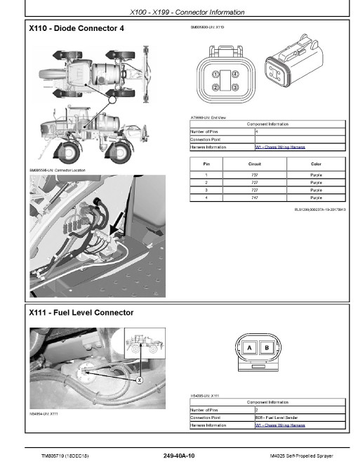
X100 - X199 - Connector Information
X200 - X299 - Connector information
X300 - X399 - Connector information
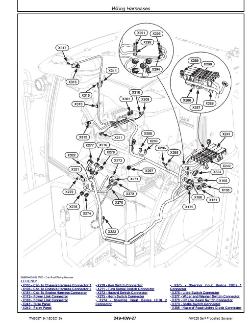
Wiring Harnesses
Power Train System
General Information
Tests and Adjustments
Theory of Operation
Schematics
Diagnostics
Power Train System - Component Information
Power Train System - Summary of References
Steering and Brakes
General Information
Test Procedures and Adjustments
Theory of Operation
Schematics
Diagnostics
Steering and Brakes - Component information
Steering and Brakes - Summary of References
Hydraulic System
General Information
Test Procedures and Adjustments
Basic Hydraulic System - Theory of Operation
Boom - Theory of Operation
Solution Pump Motor - Theory of Operation
Basic Hydraulic System - Schematics
Boom - Schematics
Solution Pump Motor - Schematics
Basic Hydraulic System - Diagnostics
Boom - Diagnostics
Solution Pump Motor - Diagnostics
Hydraulic System - Component Information
General Information
Hydraulic - A Components
Hydraulic - B Components
Hydraulic - C Components
Hydraulic - D Components
Hydraulic - F Components
Hydraulic - G Components
Hydraulic - H Components
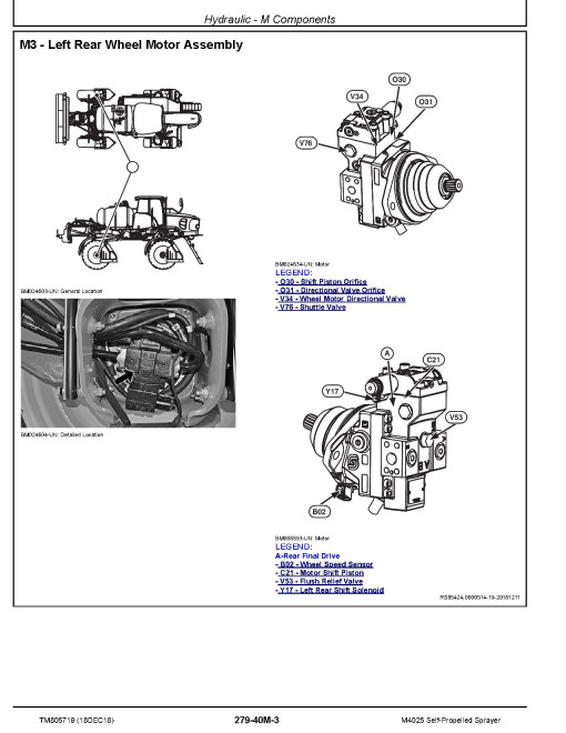
Hydraulic - M Components
Hydraulic - O Components
Hydraulic - P Components
Hydraulic - R Components
Hydraulic - S Components
Hydraulic - V Components
Hydraulic - X Components
Hydraulic - Y Components
Suspension System
General Information
Test Procedures and Adjustments
Suspension System - Theory of Operation
Suspension System - Schematics
Suspension System - Diagnostics
Solution System
General Information
Test Procedures and Adjustments
Solution System - Theory of Operation
Solution System - Schematics
Solution System - Diagnostics
Suspension System - Component Information
Tread Adjust - Component Information
Air Suspension - C Component
Air Suspension - F Component
Air Suspension - P Component
Air Suspension - R Component
Air Suspension - V Component
Solution System - Component Information
Solution System - B Components
Solution System - D Components
Solution System - F Components
Solution System - O Components
Solution System - P Components
Solution System - R Components
Solution System - V Components
Operator Station
General Information
Test and Adjustment Procedures
Air Conditioning and Heating - Theory of Operation
Air Conditioning and Heating - Schematic
Air Conditioning and Heating - Diagnostics
Operator Station - Component Information
Component Location
Service Tools
Service Tools and Kits
Section 280A
Section 280B
Section 289A
Section 289B
General
Manufacturer
John DeereDocument Type
Diagnostic ManualRegion
South AmericaLanguage
EnglishType of Equipment
Self-Propelled SprayerReviews: 0
There are no reviews for this product.
Questions: 0
No questions about this product.
Similar Products

