")
")
")
")
")
$25.00
Models
2TNV70, 3TNV70, 3TNV76, 3TNV82A, 3TNV84, 3TNV84T, 3TNV88, 4TNV84, 4TNV84T, 4TNV88, 4TNV94L, 4TNV98, 4TNV98TDocument Type
Repair Technical ManualLanguage
EnglishType of Equipment
Diesel EngineIllustrated factory Repair Technical Manual for Electrical system of Yanmar Diesel Engines Models 2TNV70, 3TNV70, 3TNV76, 3TNV82A, 3TNV84, 3TNV84T, 3TNV88, 4TNV84, 4TNV84T, 4TNV88, 4TNV94L, 4TNV98 and 4TNV98T.
This manual will assist you in assembling, disassembling, and repairing for your engine diesel or diesel engine.
You can use a Windows, Mac, or Android device to view this manual. You only need to have a PDF reader installed.
Covered Models:
2TNV70
3TNV70
3TNV76
3TNV82A
3TNV84
3TNV84T
3TNV88
4TNV84
4TNV84T
4TNV88
4TNV94L
4TNV98
4TNV98T
Format: PDF, 558 pages
Language: English
Table of Contents:
Application Standard
Application Standard
Special Operating Environment
Low-temperature startability
Engine Model Selection
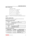
Model Designation
Engine Classification
Standard Engines for Driven Machines
Specifications
Atmospheric Conditions and Engine Configuration Affect Engine Output
Specifications
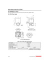
Dimensions
Correcting Observed Power
Power Corrections
Atmospheric Pressure Calculation for Change in Altitude
Atmospheric Temperature Calculation for Change in Altitude
Relationships among Altitude, Atmospheric Pressure and Atmospheric Temperature
How to Obtain Relative Humidity by Dry and Wet-Bulb Thermometer
Relationship between Atmospheric Temperature and Saturation Vapor Pressure
Altitude Characteristics
Engine Performance
Performance Curves
Torque Curve: T
Partial Recovery Ratio
Governor Performance
Cold Starting Aids
Glow Plug
Inlet Air Heater
Engine Block Heater
Cold Start Device (CSD) for MP Pump
Air Intake System
Air Capacity Required for Combustion
Air Cleaner
Air Intake Restriction
Exhaust System
EGR Equipment
Intake/Exhaust Pressure
Turbocharger
Exhaust Back Pressure
Exhaust Muffler
Fitting Precautions for Exhaust System
Exhaust Gas Volume and Exhaust Back Pressure
Black Smoke Exhaust
Cooling System
Cooling System Diagram
Engine Coolant
Radiator
Cooling System Hoses
Thermostat
Engine Coolant Temperature Switch
Cooling System Recovery Tank
Heat Rejection to Engine Coolant
Cooling Fan and Its Drive System
Diesel Fuel System
Diesel Fuel System Diagram
Standard Diesel Fuel Line Layout
Diesel Fuel
Engine Oil Filter System
Fuel Line Maintenance
Lubricating System
Lubricating System Diagram
Engine oil
Engine Oil Filter System
Oil Pan
Inclined Performance
Crankcase Breather System
Engine Oil Pressure Switch
Engine Oil Cooler
Matching Test Procedure
Purpose of Matching Test
Items Required for Test
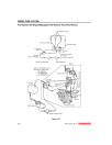
Instructions for Mounting Measuring Instruments
Preparation for Matching Test Operation
Heat Balance Test
Test Data Interpretation and Criteria
Output Matching Test
Engine Performance
Evaluation of Output Matching
Evaluation of Output Matching for General Purpose Industrial Machines
Evaluation Notes
Evaluation of Output Matching of Generator
Evaluation of Output Matching at the Maximum Ambient Temperature
Engines Compatible with Both 50 Hz and 60 Hz
Maximum Output of Generator
Vibration Measurement
Installation State Check
Electrical System
Precautions for Using Electrical Components
Starter Motor
Safety Relay
Stop Solenoid
Charging System
Regulator
Control of Battery Indicator
Battery
Wiring
Electronic Control System
Precautions on the Use of Electronic Control Components
Control System
Harness
Control Functions
Fuel Injection Pump
EGR Valve
Accelerator Sensor
Main Relay
Rack Actuator Relay
Sub Relay
Starter Relay
Starting Aid Relay
Coolant Temperature Sensor
Checklist for Eco-governor
ECU Application Menu
ON-Vehicle Communication CAN Specification
SCOPE
COMMUNICATION PROTOCOLS
MESSAGE FORMAT
Diagnostic Trouble Codes (DTCs)
REFERENCES
Appendix A
Appendix B
Appendix C
P.T.O. Systems
Direct Coupled P.T.O. Configurations
Caution for Side Load
How To Calculate the Side Load
Allowable Side Load for Main P.T.O.
Allowable Side Load for Front P.T.O.
Cautions for Hydraulic Pump Drive P.T.O. on the Gear Case
Allowable Load for Hydraulic Pump Drive P.T.O.
Vibration Isolation System
Principle of Vibration Isolation
Calculation of Rubber Isolator
Vibration Isolation Materials
Torsional Vibration
What is Torsional Vibration?
Torsional Vibration of Multi-Cylinder Engine
Actual Processing for Torsional Vibration
Avoidance and Suppression of Torsional Vibration
Torsional Vibration Equivalent Vibration System
Reference Materials
Principal Conversion Table for the Engine Specifications
Fuel Tank
Oil Pan Holding Time
Mean Piston Speed
Total Displacement
Torque
Net Mean Effective Pressure
Fuel Injection
Cyclic Irregularity (or Coefficient of Speed Fluctuation)
Thermal Efficiency and Heat Loss
Generator
Hydraulic Pump (gear)
Water Pump Driving Horsepower (Required Horsepower)
Form Characteristics of Cooling Fan
Mesh Number and Size of Mesh
Centigrade-Fahrenheit Temperature Conversion
Hill Climbing Horsepower and Allowable Climbing Angle
Conversion Factors for SI Units
This manual will assist you in assembling, disassembling, and repairing for your engine diesel or diesel engine.
You can use a Windows, Mac, or Android device to view this manual. You only need to have a PDF reader installed.
Covered Models:
2TNV70
3TNV70
3TNV76
3TNV82A
3TNV84
3TNV84T
3TNV88
4TNV84
4TNV84T
4TNV88
4TNV94L
4TNV98
4TNV98T
Format: PDF, 558 pages
Language: English
Table of Contents:
Application Standard
Application Standard
Special Operating Environment
Low-temperature startability
Engine Model Selection
Model Designation
Engine Classification
Standard Engines for Driven Machines
Specifications
Atmospheric Conditions and Engine Configuration Affect Engine Output
Specifications
Dimensions
Correcting Observed Power
Power Corrections
Atmospheric Pressure Calculation for Change in Altitude
Atmospheric Temperature Calculation for Change in Altitude
Relationships among Altitude, Atmospheric Pressure and Atmospheric Temperature
How to Obtain Relative Humidity by Dry and Wet-Bulb Thermometer
Relationship between Atmospheric Temperature and Saturation Vapor Pressure
Altitude Characteristics
Engine Performance
Performance Curves
Torque Curve: T
Partial Recovery Ratio
Governor Performance
Cold Starting Aids
Glow Plug
Inlet Air Heater
Engine Block Heater
Cold Start Device (CSD) for MP Pump
Air Intake System
Air Capacity Required for Combustion
Air Cleaner
Air Intake Restriction
Exhaust System
EGR Equipment
Intake/Exhaust Pressure
Turbocharger
Exhaust Back Pressure
Exhaust Muffler
Fitting Precautions for Exhaust System
Exhaust Gas Volume and Exhaust Back Pressure
Black Smoke Exhaust
Cooling System
Cooling System Diagram
Engine Coolant
Radiator
Cooling System Hoses
Thermostat
Engine Coolant Temperature Switch
Cooling System Recovery Tank
Heat Rejection to Engine Coolant
Cooling Fan and Its Drive System
Diesel Fuel System
Diesel Fuel System Diagram
Standard Diesel Fuel Line Layout
Diesel Fuel
Engine Oil Filter System
Fuel Line Maintenance
Lubricating System
Lubricating System Diagram
Engine oil
Engine Oil Filter System
Oil Pan
Inclined Performance
Crankcase Breather System
Engine Oil Pressure Switch
Engine Oil Cooler
Matching Test Procedure
Purpose of Matching Test
Items Required for Test
Instructions for Mounting Measuring Instruments
Preparation for Matching Test Operation
Heat Balance Test
Test Data Interpretation and Criteria
Output Matching Test
Engine Performance
Evaluation of Output Matching
Evaluation of Output Matching for General Purpose Industrial Machines
Evaluation Notes
Evaluation of Output Matching of Generator
Evaluation of Output Matching at the Maximum Ambient Temperature
Engines Compatible with Both 50 Hz and 60 Hz
Maximum Output of Generator
Vibration Measurement
Installation State Check
Electrical System
Precautions for Using Electrical Components
Starter Motor
Safety Relay
Stop Solenoid
Charging System
Regulator
Control of Battery Indicator
Battery
Wiring
Electronic Control System
Precautions on the Use of Electronic Control Components
Control System
Harness
Control Functions
Fuel Injection Pump
EGR Valve
Accelerator Sensor
Main Relay
Rack Actuator Relay
Sub Relay
Starter Relay
Starting Aid Relay
Coolant Temperature Sensor
Checklist for Eco-governor
ECU Application Menu
ON-Vehicle Communication CAN Specification
SCOPE
COMMUNICATION PROTOCOLS
MESSAGE FORMAT
Diagnostic Trouble Codes (DTCs)
REFERENCES
Appendix A
Appendix B
Appendix C
P.T.O. Systems
Direct Coupled P.T.O. Configurations
Caution for Side Load
How To Calculate the Side Load
Allowable Side Load for Main P.T.O.
Allowable Side Load for Front P.T.O.
Cautions for Hydraulic Pump Drive P.T.O. on the Gear Case
Allowable Load for Hydraulic Pump Drive P.T.O.
Vibration Isolation System
Principle of Vibration Isolation
Calculation of Rubber Isolator
Vibration Isolation Materials
Torsional Vibration
What is Torsional Vibration?
Torsional Vibration of Multi-Cylinder Engine
Actual Processing for Torsional Vibration
Avoidance and Suppression of Torsional Vibration
Torsional Vibration Equivalent Vibration System
Reference Materials
Principal Conversion Table for the Engine Specifications
Fuel Tank
Oil Pan Holding Time
Mean Piston Speed
Total Displacement
Torque
Net Mean Effective Pressure
Fuel Injection
Cyclic Irregularity (or Coefficient of Speed Fluctuation)
Thermal Efficiency and Heat Loss
Generator
Hydraulic Pump (gear)
Water Pump Driving Horsepower (Required Horsepower)
Form Characteristics of Cooling Fan
Mesh Number and Size of Mesh
Centigrade-Fahrenheit Temperature Conversion
Hill Climbing Horsepower and Allowable Climbing Angle
Conversion Factors for SI Units
General
Models
2TNV70, 3TNV70, 3TNV76, 3TNV82A, 3TNV84, 3TNV84T, 3TNV88, 4TNV84, 4TNV84T, 4TNV88, 4TNV94L, 4TNV98, 4TNV98TDocument Type
Repair Technical ManualLanguage
EnglishType of Equipment
Diesel EngineReviews: 0
There are no reviews for this product.
Questions: 0
No questions about this product.
Similar Products
")
3TNV82A, 3TNV84, 3TNV88, 4TNV106, 4TNV84, 4TNV88, 4TNV94L, 4TNV98 Tier 3 Diesel Engines Service Manual (0BTNV-G00102)
0BTNV-G00102
Models: 3TNV82A, 3TNV82A-B, 3TNV84, 3TNV84T, 3TNV84T-B, 3TNV88, 3TNV88-B, 3TNV88-U, 4TNV84, 4TNV84T, 4TNV84T-Z, 4TNV88, 4TNV88-B, 4TNV88-U, 4TNV94L, 4TNV98, 4TNV98-Z, 4TNV98-E, 4TNV98T, 4TNV98T-Z, 4TNV106, 4TNV106T
Document Type: Service Manual
Language: English
Type of Equipment: Diesel Engine
$30.00
, 3TNE88, 4TNE82, 4TNE84(T), 4TNE88 Engines Service Manual")
2TNE68, 3TNE68, 3TNE74, 3TNE78A, 3TNE82, 3TNE82A, 3TNE84(T), 3TNE88, 4TNE82, 4TNE84(T), 4TNE88 Engines Service Manual
YANMAR-TNE-SM
Models: 2TNE68, 3TNE68, 3TNE74, 3TNE78A, 3TNE82A, 3TNE84, 3TNE88, 4TNE82, 4TNE84, 4TNE88, 3TNE84T, 4TNE84T
Document Type: Service Manual
Language: English
Type of Equipment: Diesel Engine
$20.00
 Diesel Engines Engine Technical Manual (CTM130319)")
4TNV98 and 4TNV98T (iT4/Stage IIIB) Diesel Engines Engine Technical Manual (CTM130319)
CTM130319
Models: 4TNV98, 4TNV98T
Document Type: Engine Technical Manual
Language: English
Type of Equipment: Diesel Engine
$27.00
")
JDLINK/ZXLINK Machine Monitoring System Component Technical Manual (CTM10006)
CTM10006
Models: JDLINK/ZXLINK MACHINE MONITORING
Document Type: Component Technical Manual
Language: English
Type of Equipment: System
$15.00
")
Front and Rear Drive Axles Component Technical Manual (CTM10077X19)
CTM10077X19
Models: FRONT, REAR
Document Type: Component Technical Manual
Language: English
Type of Equipment: Drive Axle
$14.95